> Ethernet and RJ45 interfaces, used for PC remote control and printing test reports.
|
General Parameters |
|
|
Display |
5.7-inch TFT touch screen |
|
Scope of Working Power Supply |
100 ~ 264 V AC, 47 ~ 63 Hz |
|
Fuse |
6A |
|
Maximum Power Consumption |
300 W |
|
Communication Method |
Ethernet LAN |
|
External Control Mode |
25 needle parallel thread |
|
External Trigger Input |
BNC, 5V TTL |
|
CRO Triggers Output |
BNC, 5V TTL |
|
Operation Control Input |
BNC, 5V TTL |
|
Pulse Triggering Method |
Manual, automatic, externally triggered |
|
External Synchronous Input |
20 ~ 400 V, 45 ~ 65 Hz |
|
Warning Light Output |
Multi core connector output, matched with external alarm light module (optional) |
|
Safety Circuit |
Short circuit of safety loop, stop working when the safety loop is open circuit |
|
Failure Detection |
When it fails, the front panel LCD displays and interrupts the instrument's operation |
|
Instrument Working Status Indication |
LED indication, LCD display |
|
Instrument Grounding Connection Method |
Use a flat grounding wire |
|
Chassis Size |
6U L * W * H: 620 * 450 * 280 mm |
|
Instrument Weight |
About 50 kg |
|
Environmental Scope |
15℃ ~ 35℃ |
|
Pressure Range |
86 kPa ~ 106 kPa |
|
Humidity Range |
45% ~ 75% |
|
Built in coupling/decoupling network (single-phase fully automatic) |
|
|
EUT Carrying Capacity |
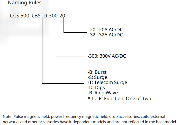
AC 300 V 20 A/32 A (optional) 50/60 Hz |
|
DC 300 V 20 A/32 A (optional) |
|
|
EUT Power Input and Output |
4mm banana plug cable |
|
EUT Voltage Monitoring Output |
BNC output, 100V: 1V |
|
EUT Current Monitoring Output |
BNC output, 10 A: 1 V |
|
Synchronization Method |
Internal synchronization, external synchronization, asynchronous |
|
Internal Synchronization |
0 °~360 °, 1 ° step setting or random mode |
|
Pulse group Coupling/decoupling |
Built in single-phase automatic coupling/decoupling network |
|
1.2/50 μs Combined Wave Coupling/decoupling |
Built in single-phase automatic coupling/decoupling network |
|
Ringing Wave Coupling/decoupling |
Built in single-phase automatic coupling/decoupling network |
|
IEC-61000-4-4 Electrical Fast Transient Pulse Test |
|
|
Test Voltage Range |
0.25 kV ~ 5 kV (±10%) |
|
Network port test voltage range |
0.25 kV ~ 4.5 kV (±10%) |
|
50 Ω Calibration Waveform |
5 ± 1.5 ns, 50 ns ± 15 ns |
|
1000 Ω Calibration Waveform |
5 ± 1.5 ns, 50 ns(- 15 / + 100 ns) |
|
Pulse Frequency |
0.1 kHz ~ 1000 kHz |
|
Pulse Group Period |
11 ms ~ 9999 ms |
|
Pulse Train Duration |
0.075 ms ~ 750 ms |
|
Experimental Mode |
Optional scheduling mode |
|
Polarity |
Positive, negative, first positive and then negative |
|
Coupling Capacitor |
33 nF |
|
IEC-61000-4-5 Surge Immunity Test |
|
|
Test Voltage |
0.25 kV ~ 5 kV (±10%) |
|
Test Current |
0.125 kA ~ 2.5 kA ± 10% |
|
Voltage Waveform |
1.2 μs ± 30% , 50 μs ± 20% |
|
Current Waveform |
8 μs ± 20%, 20 μs ± 20% |
|
Output Impedance |
2 Ω, 12 Ω |
|
Test Interval Time |
6 ~ 99 s(the shortest depends on the test voltage) |
|
Number of Experiments |
1~999 times |
|
Experimental Mode |
Optional scheduling mode |
|
Polarity |
Positive, negative, alternate |
|
Calibration Capacitor |
18 μF built-in |
|
Coupling Resistance |
0 Ω, 10 Ω |
|
Coupling Capacitor |
Built in at 9 μF and 18 μF |
|
Surge Voltage Peak Detection |
LCD display, BNC output 1000V: 1V |
|
Surge Current Peak Detection |
LCD display, BNC output 500A: 1 V |
|
IEC-61000-4-5 Communication Wave Test |
|
|
Test Voltage |
0.25 kV ~ 5 kV (±10%) |
|
Test Current |
6.25 A ~ 125 A ±10% |
|
Voltage Waveform |
10 μs ± 30% , 700 μs ± 20% |
|
Current Waveform |
5 μs ± 20%, 320 μs ± 20% |
|
Output Impedance |
15 Ω, 40 Ω |
|
Test Interval Time |
6 ~ 99 s(the shortest depends on the test voltage) |
|
Number of Experiments |
1~999 times |
|
Experimental Mode |
Optional scheduling mode |
|
Polarity |
Positive, negative, first positive and then negative |
|
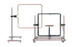
IEC-61000-4-8 Power Frequency Magnetic Field Test |
|
|
Magnetic Field Intensity |
TCXS
111 single turn magnetic field coil: |
|
TCXS
113 three turn magnetic field coil: |
|
|
Current Waveform |
50 Hz/60 Hz sine wave |
|
Current Distortion Rate |
< 5% |
|
Generator Output Current |
1 A ~ 450 A |
|
Waveform Interval Time |
1 s ~ 9999 s |
|
Test Duration |
1 s ~ 28800 s |
|
Magnetic Field Coil Size |
1 m x 1 m, other |
|
Shape of Magnetic Field Coil |
Rectangle, Other |
|
Output Magnetic Field Strength |
Scheduling Settings |
|
IEC-61000-4-9 Pulse Magnetic Field Test |
|
|
Magnetic Field Strength (1*1 m coil) |
100 A/m ~ 1200 A/m |
|
magnetic Field Strength (1*2.6 m coil) |
100 A/m ~ 880 A/m |
|
Coil Waveform (1*1 m Single Turn) |
8 μs(+ 2.4 μs /- 0.8 μs),20 μs(+ 6 μs/-2 μs) |
|
Coil Waveform (1*2.6 m Single Turn) |
8 μs(+ 3.2 μs/- 0.8 μs),20 μs( + 8 μs/ -2 μs) |
|
Test Interval Time |
5 ~ 99 s(the shortest depends on the magnetic field strength) |
|
Number of Experiments |
1~999 times |
|
Experimental Mode |
Optional scheduling mode |
|
Polarity |
Positive, negative, first positive and then negative |
|
Magnetic Field Coil Size |
1 m x 1 m, other |
|
Shape of Magnetic Field Coil |
Rectangle, other |
|
IEC-61000-4-11& IEC-61000-4-29 Cycle Drop Test |
|
|
EUT Carrying Capacity |
AC 300 V 20 A/32 A (optional) 50/60 Hz |
|
DC 100~300 V 20 A/32 A (optional) |
|
|
EUT Voltage Frequency |
45 ~ 65 Hz |
|
100
Ω Calibration Waveform |
1 ~ 5 μs |
|
100
Ω Calibration Waveform |
1 ~ 50 μs |
|
Impulse Current |
500 A |
|
Interrupt Level |
0% |
|
Temporary Voltage Drop |
0%~100% (applicable to attachment VVT/VMT series) |
|
Duration of Temporary Descent and Interruption |
0.3~9999 cycles or 1ms~9999ms |
|
Temporary Reduction and Interruption Interval Time |
50 ms ~ 50000 ms |
|
Temporary
Reductionand Interruption of |
1 ~ 9999 times |
|
Temporary
Descent, Interruption of |
1~5 μs (100 Ω load) |
|
IEC-61000-4-12 Ringing Wave Test |
|
|
Open Circuit Output Voltage (PK1) |
0.25 kV ~ 5 kV ± 10% |
|
Open Circuit Voltage Oscillation Frequency (1/T) |
100 kHz ± 10% |
|
Open Circuit Voltage Rise Time(T1,10%-90%) |
PK1 0.5 μs ± 30% |
|
Open Circuit Voltage Decay Rate |
0.4≤(PK2)/(PK1)≤1.1、0.4≤(PK3)/(PK2)≤0.8、0.4≤(PK4)/(PK3)≤0.8 |
|
Short Circuit Current Rise Time(T1, 10% -90%) |
PK1 0.2 μs ~ 1 μs |
|
Open Circuit Voltage (PK1) 5000 V When, Short-circuit Current (PK1) |
416.67 A ± 10% at 12 Ω; 166.67 A ± 10% at 30 Ω |
|
Output Impedance |
12 Ω, 30 Ω |
|
Test Interval Time |
6 ~ 99 s |
|
Pulse Frequency |
1~999 times |
|
Experimental Mode |
Optional scheduling mode |
|
Polarity |
Positive, negative, first positive and then negative |
|
CCS 500 Selection Guide List |
|||||||||
|
Host |
Compact
Immunity Test System |
IEC 61000 |
CDN single-phase three wire network |
||||||
|
-4-4 |
-4-5 |
-4-8 |
-4-9 |
-4-11 |
-4-12 |
-4-29 |
|||
|
√ |
√ |
|
√ |
√ |
√ |
√ |
√ |
||
|
Optional module |
|||||||||
|
|
Power
frequency |
|
|
√ |
|
|
|
|
|
|
|
AC
power supply |
|
|
|
|
√ |
|
|
|
|
|
Power
failure and power |
|
|
√ |
|
√ |
|
|
|
|
|
Pulse
group coupling/ |
√ |
|
|
|
|
|
|
Can root |
|
|
Lightning
surge |
|
√ |
|
|
|
√ |
|
|
|
|
Surge
and group |
√ |
√ |
|
|
|
√ |
|
|
|
|
Magnetic
field coil |
|
|
√ |
√ |
|
|
|
|
|
|
Capacitive
coupling |
√ |
|
|
|
|
|
|
|
|
Note: If only the host is selected and VVT or VMT testing modules are not available, an additional power supply is required for IEC 61000-4-11/29 testing |
|||||||||
|
List of Testing and Measurement Selection Guidelines |
|||||||||
|
Instrument name and model |
IEC 61000 |
||||||||
|
-4-4 |
-4-5 |
-4-8 |
-4-9 |
-4-11 |
-4-12 |
-4-29 |
|
||
|
|
High
voltage |
|
√ |
|
|
√ |
√ |
√ |
|
|
|
Broadband
|
|
√ |
|
√ |
|
√ |
|
|
|
|
10
kV surge |
|
√ |
|
|
|
|
|
|
|
|
EFT
pulse |
√ |
|
|
|
|
|
|
|
|
|
Immunity
|
√ |
√ |
√ |
√ |
√ |
√ |
√ |
|