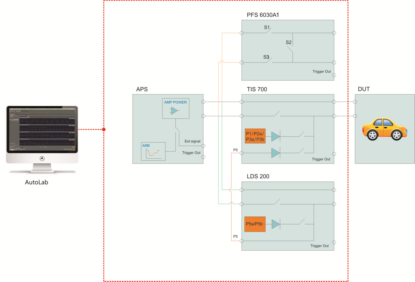
System overall connection diagram
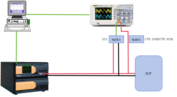
ISO 16750-2 2023 Sweep Frequency Closed Loop Layout
The naming convention for instruments is as follows, using APS 80I100DSR as an example:
APS: Four Quadrant Power Supply Voltage Change Simulator;
80 : Maximum voltage 80 V; 40:40 V, 60:60 V; (Customizable higher voltage)
I : The level representing negative voltage, D:0 V,E:-15 V,F:-20 V,G:-40 V,H:-60 V,I:-80 V;(Customizable higher voltage)
100 : Output current level, can be divided into 10 A, 30 A, 50 A, 100 A,200 A; (Customizable higher current)
D : Four-quadrant, bipolar power supply (if D is not included in the model, it is a unipolar power supply);
S : Built in AWG signal generator (without S in the model, there is no built-in signal generator);
R : The output impedance is adjustable (if there is no R in the model, the output impedance is not adjustable).
|
Technical Parameters |
|||
|
APS 40G30DSR |
|||
|
-40 V ~ +40 V |
|||
|
Output Current |
Max 30 A,continuity |
||
|
Peak Current |
60 A, duration greater than 200 ms |
||
|
Frequency Range |
DC ~ 300 kHz full frequency signal, resolution: 0.01 Hz, Accuracy: ± 5% |
||
|
Vpp |
Max 32 V(DC - 300 kHz) |
Accuracy |
< 3V ± 0.1 V |
|
Ipp |
Max 60 A |
||
|
APS 80I100DSR |
|||
|
Output Voltage |
-80 V ~ +80 V |
||
|
Output Current |
Max 100 A,continuity |
||
|
Peak Current |
200 A, duration greater than 200 ms |
||
|
Frequency Range |
DC ~ 300 kHz full frequency signal, resolution: 0.01 Hz, Accuracy: ± 5% |
||
|
Vpp |
Max 32 V(DC - 300 kHz) |
Accuracy |
< 3V ± 0.1 V |
|
Ipp |
Max 200 A |
||
|
APS 80G200DSR |
|||
|
Output Voltage |
-40 V ~ +80 V |
||
|
Output Current |
Max 200 A,continuity |
||
|
Frequency Range |
DC ~ 300 kHz full frequency signal, resolution: 0.01 Hz, Accuracy: ± 5% |
||
|
Vpp |
Max 32 V(DC - 300 kHz) |
Accuracy |
< 3V ± 0.1 V |
|
Ipp |
Max 400 A |
||
|
内部信号源 |
|||
|
Frequency Range |
DC ~ 500 kHz |
||
|
Waveform Type |
DC waveform, oblique wave, triangular wave, sine wave, square wave, sweep wave, exponential wave, oscilloscope stored data waveform, user-defined waveform editing, irregular and irregular arbitrary wave |
||
|
Can Set Waveform Parameters |
Amplitude, duration, frequency, DC offset, rectification, cycle duty cycle, phase angle, trigger |
||
|
Amplitude and Bias Changes |
Static, linear, logarithmic |
||
|
Frequency Variation |
Static, linear, logarithmic |
||
|
Start and End Phase Control |
0°~ 359°, 1° step setting |
||
|
Rectification |
None, Positive, Negative, Bridge Rectifier |
||
|
Introduce File Types |
CSV |
||
|
Introduce the Number of Waveform PointsIn the file |
8 k |
||
|
Segments that Make Up the Waveform |
Each waveform can have up to 1000 segments, and each segment can be composed of several types of waveforms |
||
|
Duration of the Segment |
DC waveform: 10 μs ~ 299 h |
||
|
Number of Times |
1 ~ 9999 times |
||
|
General Parameters |
|||
|
Analog Signal Input |
BNC, according to the actual instrument configuration, the maximum voltage is ± 10 V |
||
|
Sense Signal Input |
BNC |
||
|
Source Impedance |
10 mΩ ~ 200 mΩ (10 mΩ step)/No internal resistance |
||
|
Voltage Compensation Accuracy |
± 0.1 V |
||
|
Maximum Voltage |
4 V |
||
|
Compensation Value |
>90%, recovery time <10 μs |
||
|
Voltage Offset |
Ur<0.2 Vpp |
||
|
Voltage Fluctuation |
<3 μs/10 μs(12 V DC到13 V DC;0 V到 Vmax DC) |
||
|
Boosting Time |
LAN Ethernet and RJ45 |
||
|
Serial Interface |
1:10 |
||
|
External Signal AmplificationRatio |
15℃ ~ 35℃ |
||
|
Ambient Temperature |
45% ~ 75% ,RH(no condensation) |
||
|
Relative Humidity |
86 kPa ~ 106 kPa |
||
|
Atmospheric Pressure |
APS 40xxDSR |
APS 80xxDSR |
|
|
Working Power |
AC 220 V,±10%,45 Hz ~ 65 Hz |
AC 380 V,±10%,45 Hz ~ 65 Hz |
|
|
Dimension |
8U/450 mm(W)*380 mm(H)* 620 mm(D) |
35U/600 mm(W)*1250 mm(H)*800 mm(D) |
|
|
Weight |
约37 kg |
约150 kg |
|
|
Standard Accessories |
|||
|
Power cord,Testing Wire,Flat Grounding Wire,Feedback Compensation Wire, User Manual ,Calibration Report, Product Warranty |
|||
|
Optional Accessories |
|||
|
1 |
Automotive Immunity Testing Software |
Model: AutoLab |
|
|
2 |
Oscilloscope |
Model: TEK MDO 3000 Series |
|
|
3 |
Current Probe |
Model:CTB 200B |
|
|
Model:CTB 501B |
|||
|
Monitor current usage during ripple closed-loop. |
|||
|
4 |
Negative voltage levels can be customized except for D, E, F, G, H, and I. |
||